Sunday, October 3, 2010

Motor Cooling Blower

It has been way too long since I posted something so I thought it is time to try to catch up. Since I installed the LiFePO4 battery pack I knew it would be quite easy to exceed the 1-hour rating of the motor and over heat it. I decided to figure out how to get a cooling blower mounted and then just do it!

I had to make a shroud for the brush end of the motor. I picked up a piece of SS sheet metal from a local sheet metal shop. They cut off a strip the width I needed. It was enough to make 2 or three shrouds. I use a piece of aluminum flashing to cut out a pattern since it is easy to cut. I used this to make the SS version. I had to do this twice because I had to move the hose attachment from the top to the back of the motor. There wasn't enough clearance otherwise. The person I had make the hose attachment made it a little bigger than I was expecting but then what do you expect from a non-sheet metal worker? A one-off is much harder than something that will be made by the 1000s.

I picked up a sheet of 1/4" 6061 aluminum and cut out a piece to fit the end of the motor. I included a little extension to the bottom to accommodate mounting the blower. I had to shim the plate out from the motor to clear the shaft and housing so I used a hole saw and cut out some washers from the 1/4" sheet. I then used a piece of 1/16" aluminum to shim the bottom and left bolts to compensate for the motor support under the top and right bolts. You can see the plate below with 4 holes drilled and tapped to mount the blower motor.


The shims are visible in the picture below. The black tape around the inlet is actually rubber insulation tape which sticks to itself when it is clean. I used this to make the pipe a little larger and provide a little sealing ability. It ends up that it holds extremely well. I've tried to remove the pipe and can't get it off. Maybe the rubber melted a little, I don't know.


I picked up some aluminum flex pipe from the local wood and pellet stove shop. I wanted something which would handle the heat and be able to hold its own weight in a rough environment. I cut a PVC coupling in half and, with a short piece of pipe in it, slipped it inside the outlet. This gave me the right diameter for the aluminum hose. I put some silicon around the joint and a small sheet metal screw into the PVC coupling to make sure they didn't come apart.

My next problem was to get the splash guard to clear the new addition. The splash guard material is actually some thick #2 plastic like milk jugs are made of. I figured I could heat and stretch it into the shape I needed. I stuffed some cardboard in between the plastic and aluminum hose and used a propane torch to heat and mold the plastic. When I starts to turn clear you know it is very pliable.


Here is the result.

Just enough clearance.

The next issue is how to make sure only clean dry air gets to the blower. I wanted to pull air from outside the cabin but there just wasn't enough room to do so. It ends up that while driving I can't hear the blower over the road noise so it isn't too much of an issue. I decided to get a K&N rectangular filter and install in the back wall of the tub. The filter is designed to clamp on to a pipe but I needed to attach a flexible hose. I went to a muffler shop and had them make me an adapter out of tail pipe.

A perfect fit.

The next issue was how to mount the filter. I didn't really want anything visible and I wanted to put as few holes in the tub as I could get away with. As you can see in the pictures there isn't really anything to mount the filter to.
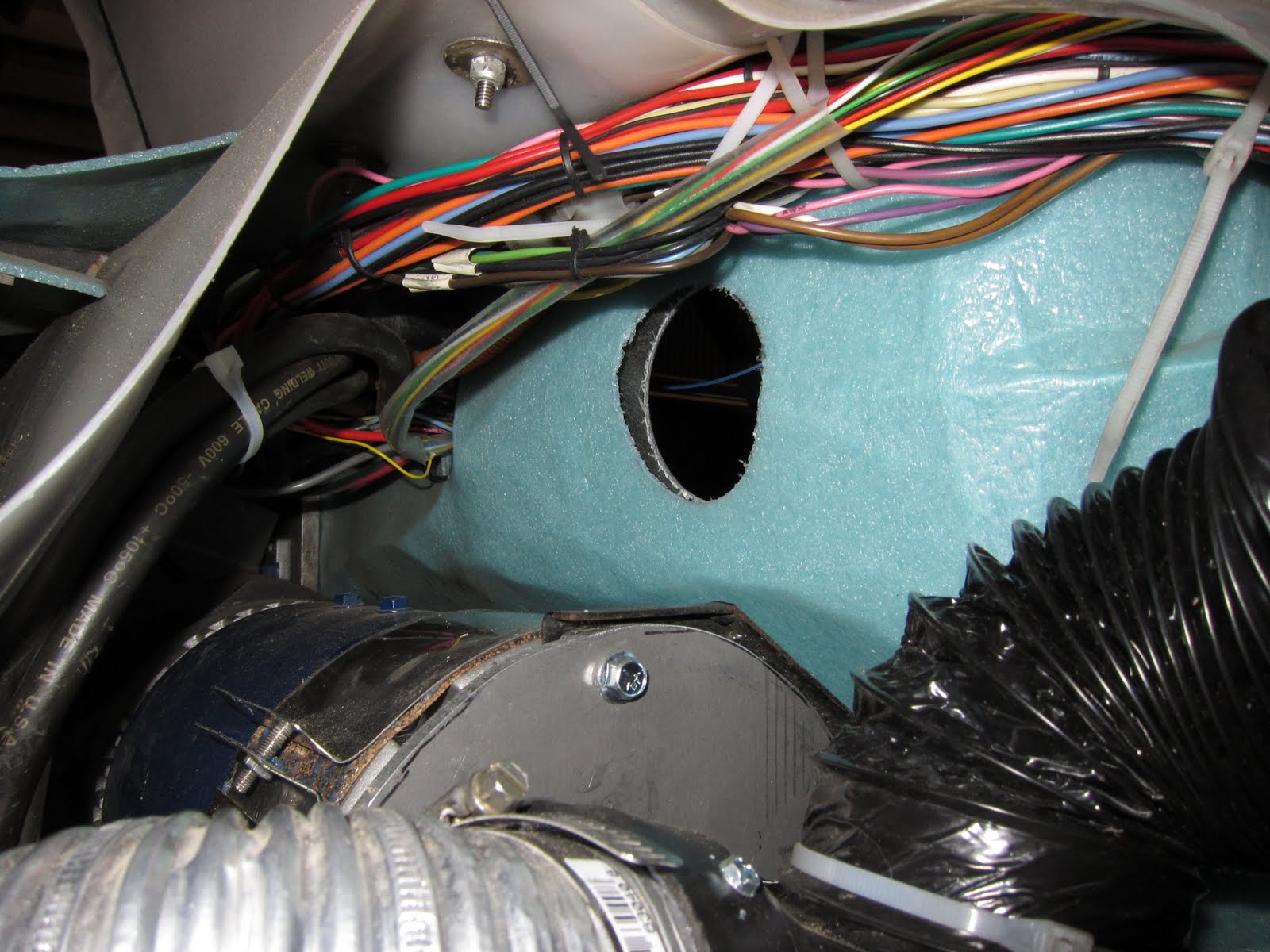
I decided to see how well the hose clamp screw would work in keeping the filter in place. The clamp had to go around the rubber of the filter and hold it to the tail pipe adapter piece. It ends up that the fiberglass is just thin enough to make this work. After more than 3000 miles I haven't had any issues with the filter moving out of place even though it wiggles some.
I used some bilge blower hose from a boat shop to connect the filter to the blower. This provides enough flexing for the motor to move up and down with the rear suspension and I only get clean dry air through the motor.
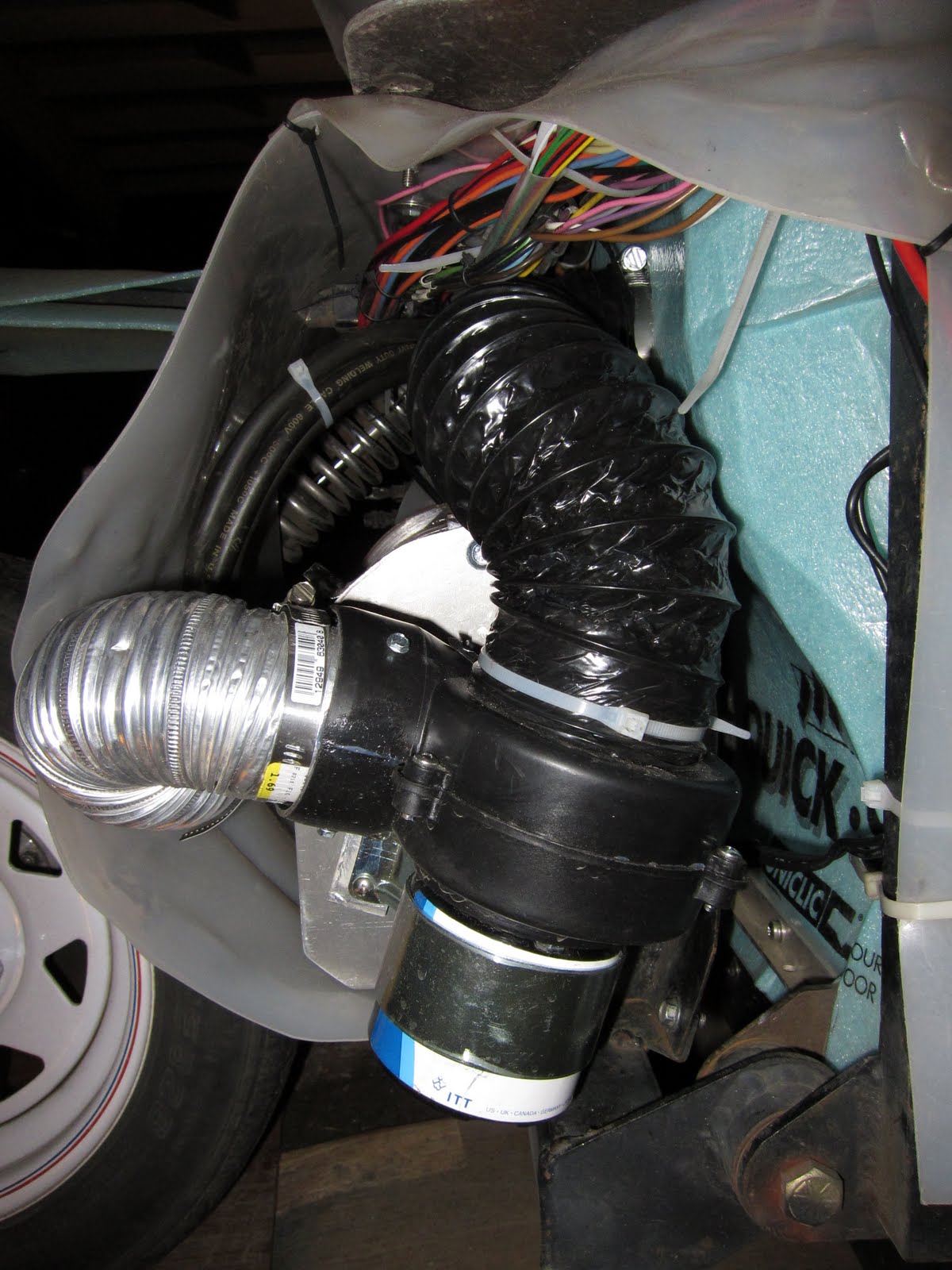
You can see in the picture above that the hose almost touches the top of the motor mount. I later added some strap material (like duct tape without the sticky) to hold the hose up off this sharp point. Below is a bottom view.

I initially started with a toggle switch on the dash to turn on the blower. I didn't want it to run all the time unless the motor needed it. The problem with this was that it was easy to forget. I decided that I would install a thermal snap switch to turn on the blower. The problem is that it is difficult to measure the hottest place on the motor since it is inside. I decided that I would install a switch on the case and use one which turned on at a cool temperature as far as motors go. I chose one which turns on at 105 degrees F. I figure this is early enough for the type of driving that I do so the inside isn't likely at a melt-down temperature yet.

The problem with snap switches is that most cannot be sealed. The one I have can be sealed but I didn't have the right material. The problem is two fold. Apparently air pressure changes cause issues with the turn on temperature and possibly case fatigue. The second issue is that most sealants give off a corrosive gas while curing causing the contacts to corrode. The snap switch needed to be placed inside a sealed or nearly sealed box of some sort. It is difficult to find a small aluminum container of the right size. I finally cut the end off of an empty small butane cylinder. I used a socket to flatten the bottom of the bottle and presto, I have a can!

I was going to mount this to the brush end of the motor but a quick call the Jim Husted of Hi-torque Electric convinced me I needed to mount it to the side of the motor case. You can see the hole I had prepared in the 1/4" aluminum plate. Now a new issue arose. How to mount a flat bottomed can to a curved surface. I decided I could make a mount out of a scrap piece of 1/4" aluminum sheet and bolt it to the motor case. Since my motor is a 6.7" diameter motor I mounted a 7.25" saw blade on my radial arm saw. I clamped the sheet of aluminum to the deck of the saw and locked the blade at a 90 degree angle. I slowly moved the saw blade sideways on the aluminum plate, lowering it slightly with each pass until I had a deep enough curve in the plate. A little smoothing out with a dremel tool and I had my mount. It didn't fit exactly but it fit close enough for what I was using it for. I drilled and tapped two 4-40 holes in the case and put two hex cap screws through the snap switch ears, aluminum can, and mount into the motor case. I put a small rubber grommet in the side of the can and ran my wires inside to the snap switch. Aluminum tape sealed the top of the can. The only water entry point would be through the grommet but I rarely get any there. The switch should work fine for a long time. At least I can change it easily if needed.


The yellow wires run to a 12V relay which turns on the blower fan. I actually installed an on-of-on toggle switch in the dash. The up position turns on the fan bypassing the thermal switch. The middle forces the fan off. The lower position is for auto, where the thermal switch controls the blower. The problem is that I can still forget to turn the switch to auto if I have turned it off for some reason. I tried a small 12V incandescent bulb across the "auto" position but the problem is that there is enough current through the bulb to pull in the relay. I found a small LED at Radio Shack with a resistor attached for 12V use. This works. If the fan switch is in the off position the LED will light when the snap switch closes. Turning the switch to the ON or AUTO position will turn off the LED because it will no longer have a 12V difference across its leads. Now I just have to mount the LED in the dash.

Saturday, February 6, 2010

Efficiency differences

When I bought this Gizmo in August 2006 it came with 6 Trojan T-875 8v batteries which were 1-2 years old. One of the things I did from the beginning was to use a Kil-a-Watt meter to record the energy I pulled out of the wall. I wanted to know how much it was costing me to charger my car and to see what the efficiency was. My regular commute is 4.4 miles with an elevation change of about 450 feet, most of that is in the span of about a mile. Sometimes my Wife drives the Gizmo to work and her commute is 9 miles. I mention this because with lead acid batteries and the Zivan NG1 charger I have, every charge cycle includes an equalization phase were the batteries are gently over charged to help all of the cells reach the same state of charge. This means that with shorter drives the wasted energy is not spread out over as many miles. Furthermore, the hill climb at the end of my commute where I would routinely see 250 battery amps, a less efficient current to pull since so much energy is lost to heat, would also not be spread out over as many miles as a longer commute would give.

From August 2006 through August 26, 2009 I used the Trojan T-875 batteries. On July 29, 2009 I didn't realize the range of the pack had diminished so far and ended up reversing a cell in one of the batteries. I never was able to revive it. At that point I took the Interstate Batteries U2200UTL pack out of Gizmo #26 I purchased last summer from Galactic Pizza in Minneapolis, MN and installed it in Gizmo #31 and used them until January 18, 2010 when I installed the TS-LFP100AHA pack. (Gizmo #26 needs extensive restoration.) BTW, if you are in Minneapolis go to Galactic Pizza and get some pizza. It is excellent! Tell them that the guy from Washington who bought one of the Gizmos sent you. Besides, you will be supporting a business which uses EVs to deliver pizzas as long as weather permits.

Note that the energy values below are all as measured from the wall so include charging inefficiencies.

2006
Total Miles: 967
Total kWh: 272.81
Average miles/kWh: 3.54
Average Wh/mi: 282.1

2007
Total Miles: 2364
Total kWh: 682.15
Average miles/kWh: 3.47
Average Wh/mi: 288.6

2008
Total Miles: 497
Total kWh: 138.53
Average miles/kWh: 3.59
Average Wh/mi: 278.7
(On March 28 I sent the NORM Circuit, which reads the hall effect throttle sensor and sends the appropriate signal to the controller, to Black Sheep Technology to get a replacement built. I didn't realize at the time that I could have kept using the old one with my manual override switch until the new one arrived so I was without a Gizmo until April 2009. The new interface was worth the wait!)

2009 (8V T-875 pack)
Total Miles: 1180
Total kWh: 315.47
Average miles/kWh: 3.74
Average Wh/mi: 267.4

2009-2010 (6V U2200UTL pack)
Total Miles: 1180 (This number isn't a typo. I had to double check it, too.)
Total kWh: 294.24
Average miles/kWh: 4.01
Average Wh/mi: 249.4

2010 (TS-LFP100AHA buddy paired pack)
Total Miles: 823
Total kWh: 135.37
Average miles/kWh: 6.08
Average Wh/mi: 164.5
(January 18, 2010 through March 29, 2010)

There some interesting things I notice about the data. First 2007 showed slightly more energy use per mile than the previous year. The Gizmo came with a 30 tooth drive pulley and in August of 2007 I had to have the motor rebuilt by Jim Hustead of Hi-torque Electric in Redmond, OR. This is the Jim of White Zombie fame and the builder of the Jim-Pulse line of Warp motors. With a 30T pulley the motor was turning too slow to keep it cool. I went to the smallest pulley I could find which was a 22T pulley. This changed the gear ratio from 3:1 to 4.09:1. The motor has been much happier. I think that the build-up of carbon dust and wearing & cracking of brushes may have had something to do with the lower efficiency.

I think it is interesting that even though the T-875 pack was aging that the efficiency showed an improvement over the previous years (except for 2007). When I look at the energy used to charge after my 4.4 mile commute, however, the energy consumption was up slightly from earlier years and similar weather conditions.

When the 6V battery pack was installed I saw right away a drop in energy consumption. At first I was expecting to see the energy consumption increase because I added over 120lbs to the weight of the Gizmo. After some thought, I think the reason that the energy consumption decreased is that the significant increase in plate area meant that the 250A draws actually reduced the current per unit of plate surface area so not as much energy was lost due to resistance. This is definitely a variable one might consider when choosing a battery pack. Lighter is not necessarily going to be more efficient. Of course I only have one data point to support this hypothesis.

The biggest shock :) came when I looked at the energy use with the TS batteries. To go from a best case of 250Wh/mi with the 6V lead acid pack to a tiny 165Wh/mi is incredible! I am including all the energy I've put into the TS pack so that if I don't completely charge the pack on one charge it will be made up for when the pack gets fully charged later. I keep thinking something is wrong. I'm using the same Kil-a-Watt meter I have been using all along. Maybe I should hook a second one in series with the first to see if they both give the same results. I'm going to periodically update the data as I get more use on the pack. The only things I've come up with as to why the efficiency is so much higher is that there is very little wasted energy when charging a Lithium Ion pack. I don't equalize each time. I plan on doing that this summer to see how far out of balance the pack has gotten. I'll probably only equalize once or twice each year since the BMS will alert me to an out of balance cell. One other possibility is that with the higher voltage I went to, the controller and motor are more efficient. I really don't know how much more efficient they are but I assume a little more. On the other hand, I don't drive full throttle as much either so the switching losses would be higher, I'm guessing. Time will tell.

(edit: updated energy consumption & distance values March 31, 2010)

Performance is WAY UP!

I haven't finished installing everything in the Gizmo yet. I still have a little wiring to do on the BMS warning system, I don't have an emeter type device yet, I don't have a latching relay to kill the AC to the charger if something goes wrong, and I don't have the charger installed yet since I'm still fiddling with the finish voltage trim pot. It is finishing at about 71V right now so it isn't going too high for the BMS modules on a balanced pack. [(7-25-2010) see comments below about this ending voltage.] I have 18 "cells" and the BMS modules have a HVT (High Voltage Trip) of 4.00V. When I get things finished, or nearly so, I'll go weigh it at the Airport. A friend of mine is an A&P mechanic. He has some scales he uses to calculate the weight & balance on airplanes. I will post the data along with my CG calculations for the 6V pack and the new pack. Suffice it to say, the Gizmo is much lighter than it was with the lead acid pack.

Each pack of 10 cells with connecting straps & bolts weighs 80lbs I have a total of 36 cells. With the mounting hardware I used I figure this pack weighs about 300lbs. The Interstate Batteries U2200UTL are 62lbs each so 8 of them were 496lbs and this is without the connecting cables. It looks like I was able to reduce the weight buy about 200lbs. This is lighter than with the original Trojan T-875 batteries. They are 63 lbs each so a total of 378lbs.

The 18 "cells" I went to raised the voltage I see to about 61V nominal. After a short run to drain off the top 1% of charge or so the pack sits about 61V. After a several mile run it sits at about 60V. I find that while cruising along at about 125A or so the voltage sags to about 56-57V. A 200A load (this is 1C since I'm using buddy pairs) lowers this to about 55V. This is with the batteries at 45-50°F. Maybe when things warm up they won't sag as much. Even with this, it is much better than with the lead acid batteries.

My top speed on level roads with no wind is about 42 mph. Just after I installed the pack it appeared to be about 45-48mph so maybe the batteries were still warm from being in my shop. With the higher voltage I'm seeing current readings a little lower than before. This is to be expected. When climbing my hill I now only slow to 33mph where before I slowed to 24mph on a fully charged pack. I attribute the climbing performance to a higher voltage and being 200lbs lighter.

After installing the pack I didn't get a chance to back off on the spring tension on my coil-over shocks. I definitely sat higher and it seemed that I could feel every pebble on the road. I think I only had a 1/4" travel before the rear shock was at its maximum extension. I have since reduced the tension a couple of notches but I still ride a little higher and it is still a little stiff. I'm going to reroute the wires going to the motor so that I have more travel before the motor bottoms out against the tub of the Gizmo and the lower the tension in the spring to see how that feels.

Acceleration is much better than before. I have to watch my speed-o-meter to make sure I don't get a speeding ticket now. I can easily out accelerate the other cars on the road now. I'm not drag racing them but just comparing to what the typical driver does when a light turns green. When accelerating with the lead acid pack I almost never saw 400A from the batteries. Now I can pull 400A on every acceleration if I want. I tried bumping up the maximum amperage to the armature to 500A and noticed significant increase in acceleration. I didn't leave it there, however, since I want to stay below 2C on these batteries. I need them to last several years longer than the lead acid batteries did to recoup my investment.

In short. I love having a Lithium Ion battery pack!

Tuesday, January 26, 2010

New Batteries are finally in!

I finally have my TS-LFP100AHA batteries in my Gizmo! I still have some wiring and electronic installation to do but I'm at least driving it. I'll do another post on the performance improvements.

I had my battery box sandblasted and then I painted it with etching primer and coated it with some reasonably durable spray paint. All this time I've been trying to figure out how to mount the batteries without bolting through the bottom of the battery box. There isn't much clearance under the box and seeing the deep scratches on the bottom I felt that if I high-centered on something I could do some damage to the box and possibly the batteries as I sheared off a bolt head or something. After talking to several people I finally settled on the idea of mounting the batteries to a 3/4" sheet of exterior plywood. I made sure to get at least 7 ply so that it would be reasonably stiff. The aluminum box bottom was bowed down about a 1/2" or more and I didn't want a flexible bottom for the batteries to sit on. I put 3/4" of rigid insulation board under the plywood.

Next I needed to figure out some way to bolt the batteries to the board. I didn't want anything conductive at the top of the batteries. Someone suggested wide nylon straps over the center of each string of batteries but I couldn't come up with a way to attach the straps and then a way of tightening them. I tried building a frame around each set with holes to bolt through to the plywood but then I didn't have enough room to fit all the batteries in. I finally ended up with a 3/4" strip of aluminum between each row of batteries and a 3/4" angle aluminum on the ends. the holes you see in the plywood are for some 1/4" x 20 cap head bolts. I installed some Tee nuts in the plywood for the bolts to go into. You can also see the 3/4" angle aluminum I used on each side of the board to hold it down. I put three bolts through each side of the box and through the angle aluminum to hold things in place.

I did several test fits of the batteries to make sure everything was going to fit. Below you can see one of the middle bars. This one is 1/8" thick because I couldn't get 1/4" x 3/4" aluminum bar stock. I finally ordered some from McMaster-Carr because I didn't like how flimsy the 1/8" bar was.
When I test fit the batteries I still had about a 1/4" at each end of the box. I needed a way to make sure that the 3/4" angle aluminum end pieces didn't slip off the narrow ledge of the batteries so I made some 1" x 2" x 3/4" shims and attached them to the angle aluminum at each bolt location. As it turned out I had to use 1/8" on the other side of the box. In the picture below you can also see one piece of the 3/4" insulation installed under the hold down strip.
After thinking about the fact that aluminum conducts heat quite well I decided to look for something else for the shims. I found that McMaster-Carr had some 1/4" ABS plastic so I ordered a 2' piece and replaced the shims as shown below.


Because of voltage limitations I could not fill the whole box with 40 cells. I decided to start with 18 buddy pairs which left a hole. Below is what I did to keep the ends of the hold down straps from slipping off the battery slot edge. I used some aluminum pipe for spacers.

Here is a picture between the batteries. They are tightly packed together and don't seem to move at all when I try to move them out of place. I'll be checking them regularly to make sure the hold down method is working. If it doesn't work, I can use some threaded rod and get some non-conductive rigid material to hold the batteries from the top edge.
Here are the batteries in the battery box before I installed 3/4" insulation around the edges.


Battery straps installed. Notice the orange 1 gauge cable to the front set of 8 cells. I turned around the front set so that the positive end of the pack wasn't against the front edge of the box. The front set of cells is not easily accessible through the battery access hole in the tub of the Gizmo. Since I had to use a cable any way it was an easy thing to do. If you look closely at some of the bolts you will see a little hole in them. This is a tapped hole which the BMS modules will attach with.

The Black Sheep Technology BMS modules are installed and I'm giving the pack the first charge as a pack. Earlier I charged all the cells up to 4.00V with a bench top power supply and then put a load on them until the first BMS module gave a low voltage trip. I then disconnected the batteries and measured their voltages to 3 decimal places and ranked them based on voltage. I paired the highest voltage with the lowest, then the next highest with the next lowest and so on until I had my 18 buddy pairs. I'll check them again in a year or so. While this isn't the best way to measure capacity it is what I had. I used several 500W shop lights and a bank of ceramic base light bases as my load. 100Ah is a lot of energy to dissipate! It took quite a while.
If you look carefully at the photo below and compare it to the one above you will see that I moved a couple of BMS modules in the second row from the back. This is the second row from the bottom of the picture above and second row from the top of the picture below. The reason is that I wanted to get the whole pack to the same SOC and my Zivan NG1 wasn't working too well for that since it wanted to see a 48V pack of lead acid batteries. I used my bench top power supplies to charge two parts of the pack and I didn't know if there would be an issue with both hooked together in series. They are supposed to be able to be put in series or parallel but I accidentally hooked up my battery pack backwards and burned out the series parallel circuitry in my dual power supply unit :(. It will be going in for repair soon. By moving a couple of BMS modules I can now split my pack at the 8 pair mark without having to remove any BMS modules. Two bolts out, remove the connecting strap and I'm done. In the photo below you can see the BMS interconnecting wires. I still have to hook up the +12V, fuse, and HVT and LVT test buttons at one end of the string and the HVT, OK, LVT circuitry to the other end. The small black wire coming in from the top center of the photo goes to the "outdoor" probe of a digital thermometer to measure pack temperature. The blue-green foam piece in the center of the pack is holding the probe against the second row of batteries. The black and red wires which join and trail off the bottom of the picture are to my volt meter. I've been playing around with the voltage trim pot on my Zivan NG1. So far I have it so that it is charging less than 0.5A when the pack hits 71V. I want to stop sooner, however since this is 3.944vpc. If I turn the voltage down sooner then my pack doesn't get fully charged. I may send in the charger to get it reprogrammed.
BTW, the picture above is of the battery pack installed in the Gizmo. That is why you cannot see the front row of batteries.

Coming up...

  • Performance comparison
  • weight change
  • efficiency differences

Sunday, December 27, 2009

Cleaning the Battery Posts

Since aluminum oxide is quite non-conductive I decided to clean all of the battery posts on my new TS-LFP100AHA batteries. You can see the surface oxidation on each of the battery posts in the sample photo below. The post on the left is the negative post, and on the right is the positive.Even though copper oxide is relatively conductive I decided to clean it as well. I preparation to do the cleaning I had ordered a stainless steel wire brush, fine single cut file, and a bottoming spiral M8x1.25 tap for the post threads. I first used the wire brush to clean off each post. I could have stopped there but I wanted to make sure I had a smooth surface for the copper straps to rest against. I put a thin layer of NOALOX on each post and then used my file to smooth off the top of each post. The NOALOX helped keep the aluminum from sticking to hard in the file grooves and also put a thin layer back immediately on the aluminum to minimize oxidation. Using the fine turned out to be a good thing. I found a battery where the center post didn't stick above the nut which holds the post in place. I found the nut on each post significantly looser than on other batteries. I'm glad I discovered this since I wouldn't want the post to allow air inside and/or work loose.

After filing the tops and putting a coat of NOALOX on each post. I then put NOALOX in each hole using a cotton swab. I followed this with the tap then a cotton swab again to get any filings out of the hole followed by NOALOX again. This may have been overkill but I did find that there was a significant amount of inconsistency in the threads. I don't think it would have made a difference in getting the bolts to work but I wanted good conduction to the bolts. I'm using a BMS from Black-Sheep Technology which mounts on top of a brass bolt with a tapped hole for a screw which holds the BMS module. I have the BMS version for the TS-LFP90AHA which has the same post spacing as the 100AH battery. The brass bolt makes sure I get good conduction to the BMS module and having the screw in the bolt makes sure I don't over stress the pcb.

Right now I have the batteries hooked up in two separate parallel strings getting their initial 4.2v charge as required by the TS documentation. I have one string hooked up to my bench top lab power supply and the other set hooked up to a 4.2V smart charger. I initially did a bulk charge up to around 4 vpc using my Zivan NG-1. So far I have pulled well over 14KWh from the wall. [edit: I do not recommend charging any LiFePO4 cell to 4.2V. Even TS has lowered their max voltage to 4.0V. It shortens their life and there is very little energy above 3.45v any way. I'm now only charging to 3.485vpc. See my January 2011 blogs.]

Now I'm working on a way to mount the batteries in the Gizmo battery box. The lead acid batteries were not bolted down, nor was the battery box. It just sat in the Gizmo frame. I don't want the Li batteries bouncing up and breaking a BMS board or something if I hit a big bump.

Thursday, December 24, 2009

Lithium Batteries Finally Arrived!

Thanks to the hard work of EV Components I finally have 40 TS-LFP100AHA cells for use in the Gizmo. I placed the order in September 2009 but due to several circumstances out of their control the shipment didn't arrive until now. Fortunately they were able to find a shipper who would ship to Seattle and customs didn't take a full month like it did on earlier shipments. Dave Kois, of EV Components was kind enough to let me drive up to pick them up today. I arrived while the truck was still unloading. They sure have their work cut out for them. Look at all those boxes of cells!

While unloading the forklift ran out of propane so they had to run fill the tank. They are anxious to get an electric forklift so this doesn't happen and also so they don't have to breath the fumes. Below is another picture. You can see the brand new Toyota RAV4 that Dave is converting.

Below are pictures of my cells in my 2000 Honda Insight. It was definitely over gross. I'm glad I'm not that heavy of a person. There wasn't much spring travel left.
The box in the back is the battery box out of the Gizmo. I took it out and had it sand blasted. The bottom and corners were badly eaten by battery acid. It will last much longer with Li batteries in it. I'm going to paint it black inside and out. I'm also planning on plugging the drain holes so that water doesn't get in from the bottom. I still need to put in a splash guard in front of the box so the batteries stay clean and dry. Last time I had the batteries out I put baking soda on the bottom of the box. When I pulled them out the entire bottom was wet with baking soda crystals on the sides of most of the batteries. I determined that most of the water entered from the two front drain holes which are right where the tires would splash water on the box.

Well, I'm off to get my batteries ready to install. I still have several things to do.
  • Primer and paint the battery box
  • drill mounting holes in the battery box to match up with some threaded holes in the frame of the Gizmo so the box doesn't bounce around. Even 500lbs of batteries would bounce on some of the bumps I've hit.
  • clean off the battery posts and coat with NOALOX. I'm going to use a very fine file for this with NOALOX on the file so the aluminum won't have time to oxidize.
  • Run an M8x1.25 bottoming tap down each hole to clean the threads. I'll use NOALOX here too. The BMS I'm planning on using will mount to the top of brass bolts which hold the connecting straps so I want good conductivity through the bolts.
  • connect the batteries up in parallel and give them their 4.2V initial charge. I have a lab power supply I can use. I also picked up a 4.2V Chinoz Smart Charger from EV Components to do this.
  • Rebundle the batteries in the arrangement I need to buddy pair them.
  • finalize my mounting design and mount the the batteries to the battery box.
  • It may not matter much but I'm going to put NOALOX on the ends of all of the connecting straps. They are four layers laminated with some shrink wrap. See the picture below.

I have several other things to do but I'll post about them later.

Sunday, November 15, 2009

Battery failure ==> new pack

This summer my wife drove to work and back and then drove back to near work again to meet me at a store. Unfortunately there was no charging done in between trips. Normally this double trip would not have been a problem. I've gone 20 miles on a charge in the summer before with no problem. Apparently my range has decreased significantly. On my way home my PakTrakr gave me a message that battery #2 needed to be charged. I should have turned around and gone back to the Cowlitz PUD building where there are some EV charge plugs and plugged in for a while. Instead I tried to nurse the Gizmo home but I had one bridge to climb up and over and then 450 feet of elevation to gain on top of that. Well, one cell in battery #2 doesn't bubble on equalize anymore. I think I reversed the cell climbing the hill. Fortunately, my son and I picked up Gizmo #26 in Minneapolis, MN this summer. It had an aging pack of 6V flooded batteries which I've installed for now. I have a pack of TS-LFP100AHA on order from evcomponents.com. They are supposed to arrive the end of November 2009. I hope to have them installed durning my Christmas break.

While I had the batteries out I discovered a couple of things. First, the bottom of the aluminum battery boxes were badly etched from battery acid. I recommend that if you have metal battery boxes that you check them regularly for potential structural problems. Also, the battery box from the Gizmo I picked up in MN had cracked welds on all four corners. The Gizmo had been used as a pizza delivery vehicle so it has significantly more miles than Gizmo #31 does but it is another structural item to check.