It has been way too long since I posted something so I thought it is time to try to catch up. Since I installed the LiFePO4 battery pack I knew it would be quite easy to exceed the 1-hour rating of the motor and over heat it. I decided to figure out how to get a cooling blower mounted and then just do it!
I had to make a shroud for the brush end of the motor. I picked up a piece of SS sheet metal from a local sheet metal shop. They cut off a strip the width I needed. It was enough to make 2 or three shrouds. I use a piece of aluminum flashing to cut out a pattern since it is easy to cut. I used this to make the SS version. I had to do this twice because I had to move the hose attachment from the top to the back of the motor. There wasn't enough clearance otherwise. The person I had make the hose attachment made it a little bigger than I was expecting but then what do you expect from a non-sheet metal worker? A one-off is much harder than something that will be made by the 1000s.
I picked up a sheet of 1/4" 6061 aluminum and cut out a piece to fit the end of the motor. I included a little extension to the bottom to accommodate mounting the blower. I had to shim the plate out from the motor to clear the shaft and housing so I used a hole saw and cut out some washers from the 1/4" sheet. I then used a piece of 1/16" aluminum to shim the bottom and left bolts to compensate for the motor support under the top and right bolts. You can see the plate below with 4 holes drilled and tapped to mount the blower motor.

The shims are visible in the picture below. The black tape around the inlet is actually rubber insulation tape which sticks to itself when it is clean. I used this to make the pipe a little larger and provide a little sealing ability. It ends up that it holds extremely well. I've tried to remove the pipe and can't get it off. Maybe the rubber melted a little, I don't know.

I picked up some aluminum flex pipe from the local wood and pellet stove shop. I wanted something which would handle the heat and be able to hold its own weight in a rough environment. I cut a PVC coupling in half and, with a short piece of pipe in it, slipped it inside the outlet. This gave me the right diameter for the aluminum hose. I put some silicon around the joint and a small sheet metal screw into the PVC coupling to make sure they didn't come apart.

My next problem was to get the splash guard to clear the new addition. The splash guard material is actually some thick #2 plastic like milk jugs are made of. I figured I could heat and stretch it into the shape I needed. I stuffed some cardboard in between the plastic and aluminum hose and used a propane torch to heat and mold the plastic. When I starts to turn clear you know it is very pliable.


Here is the result.

Just enough clearance.

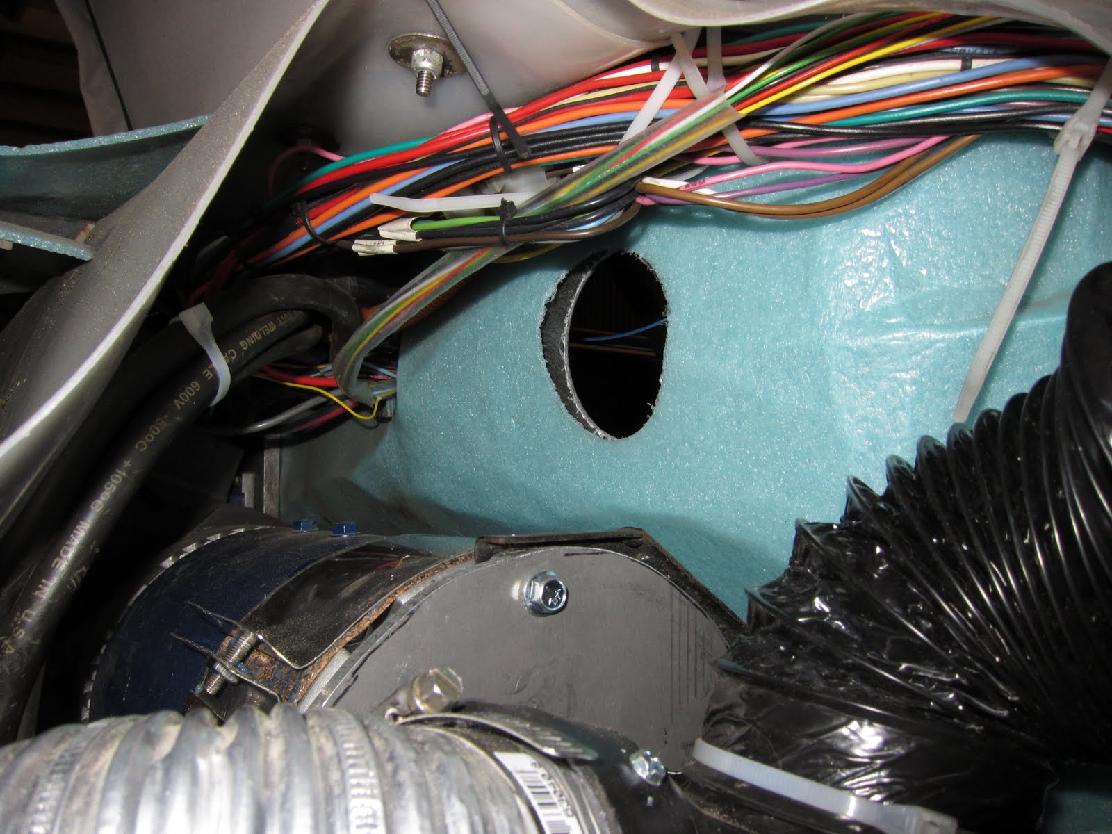
The next issue is how to make sure only clean dry air gets to the blower. I wanted to pull air from outside the cabin but there just wasn't enough room to do so. It ends up that while driving I can't hear the blower over the road noise so it isn't too much of an issue. I decided to get a K&N rectangular filter and install in the back wall of the tub. The filter is designed to clamp on to a pipe but I needed to attach a flexible hose. I went to a muffler shop and had them make me an adapter out of tail pipe.

A perfect fit.

The next issue was how to mount the filter. I didn't really want anything visible and I wanted to put as few holes in the tub as I could get away with. As you can see in the pictures there isn't really anything to mount the filter to.

I decided to see how well the hose clamp screw would work in keeping the filter in place. The clamp had to go around the rubber of the filter and hold it to the tail pipe adapter piece. It ends up that the fiberglass is just thin enough to make this work. After more than 3000 miles I haven't had any issues with the filter moving out of place even though it wiggles some.

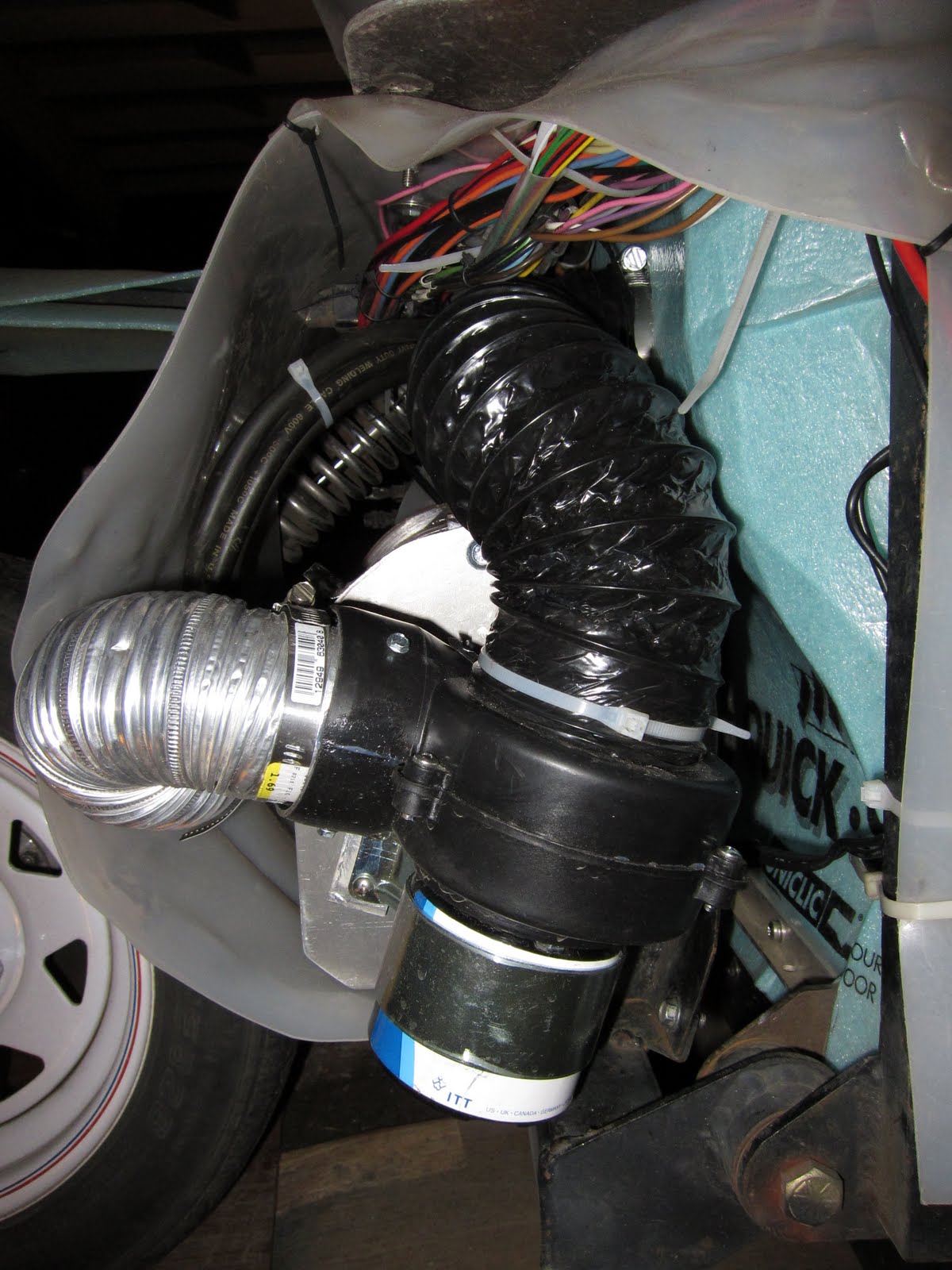
I used some bilge blower hose from a boat shop to connect the filter to the blower. This provides enough flexing for the motor to move up and down with the rear suspension and I only get clean dry air through the motor.


You can see in the picture above that the hose almost touches the top of the motor mount. I later added some strap material (like duct tape without the sticky) to hold the hose up off this sharp point. Below is a bottom view.

I initially started with a toggle switch on the dash to turn on the blower. I didn't want it to run all the time unless the motor needed it. The problem with this was that it was easy to forget. I decided that I would install a thermal snap switch to turn on the blower. The problem is that it is difficult to measure the hottest place on the motor since it is inside. I decided that I would install a switch on the case and use one which turned on at a cool temperature as far as motors go. I chose one which turns on at 105 degrees F. I figure this is early enough for the type of driving that I do so the inside isn't likely at a melt-down temperature yet.
The problem with snap switches is that most cannot be sealed. The one I have can be sealed but I didn't have the right material. The problem is two fold. Apparently air pressure changes cause issues with the turn on temperature and possibly case fatigue. The second issue is that most sealants give off a corrosive gas while curing causing the contacts to corrode. The snap switch needed to be placed inside a sealed or nearly sealed box of some sort. It is difficult to find a small aluminum container of the right size. I finally cut the end off of an empty small butane cylinder. I used a socket to flatten the bottom of the bottle and presto, I have a can!
I was going to mount this to the brush end of the motor but a quick call the Jim Husted of Hi-torque Electric convinced me I needed to mount it to the side of the motor case. You can see the hole I had prepared in the 1/4" aluminum plate. Now a new issue arose. How to mount a flat bottomed can to a curved surface. I decided I could make a mount out of a scrap piece of 1/4" aluminum sheet and bolt it to the motor case. Since my motor is a 6.7" diameter motor I mounted a 7.25" saw blade on my radial arm saw. I clamped the sheet of aluminum to the deck of the saw and locked the blade at a 90 degree angle. I slowly moved the saw blade sideways on the aluminum plate, lowering it slightly with each pass until I had a deep enough curve in the plate. A little smoothing out with a dremel tool and I had my mount. It didn't fit exactly but it fit close enough for what I was using it for. I drilled and tapped two 4-40 holes in the case and put two hex cap screws through the snap switch ears, aluminum can, and mount into the motor case. I put a small rubber grommet in the side of the can and ran my wires inside to the snap switch. Aluminum tape sealed the top of the can. The only water entry point would be through the grommet but I rarely get any there. The switch should work fine for a long time. At least I can change it easily if needed.


The yellow wires run to a 12V relay which turns on the blower fan. I actually installed an on-of-on toggle switch in the dash. The up position turns on the fan bypassing the thermal switch. The middle forces the fan off. The lower position is for auto, where the thermal switch controls the blower. The problem is that I can still forget to turn the switch to auto if I have turned it off for some reason. I tried a small 12V incandescent bulb across the "auto" position but the problem is that there is enough current through the bulb to pull in the relay. I found a small LED at Radio Shack with a resistor attached for 12V use. This works. If the fan switch is in the off position the LED will light when the snap switch closes. Turning the switch to the ON or AUTO position will turn off the LED because it will no longer have a 12V difference across its leads. Now I just have to mount the LED in the dash.
 A tear in the belt all the way to the middle. It looked like the center string was not severed but the rest were.
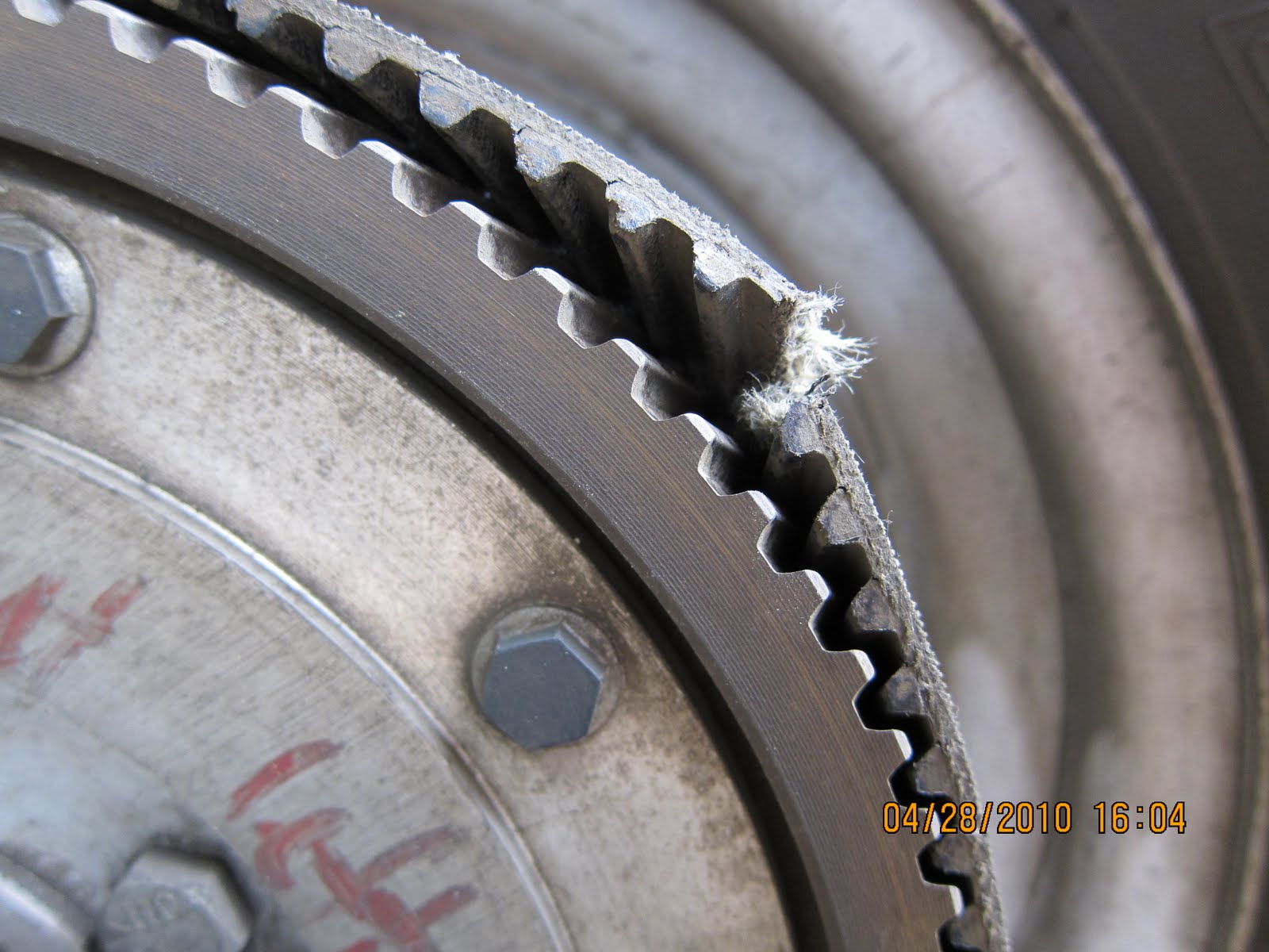 As you can see the belt lifted quite away off the pulley. I think that I was saved by the fact that the belt was on the drive pulley a short time so didn't have a chance to slide off and that the rear wheel pulley was large enough that the belt didn't slide off.
 When I took the belt into the local Applied.com store to pickup a replacement W-1280 belt the man who helped me said that it was very likely that the screw I saw got caught in the belt and tore it. Click the link to go right to the catalog page with the belt the Gizmo uses. I'm fortunate enough to have one of their stores right in town. The belts are not cheap but spending $95 for a belt rather than the retail of $130 I was happy. Maybe that is why there is retail pricing. It is so you feel great getting a deal when you pay less. In addition to the belt I asked about a tension measuring tool. The one they listed was a frequency measuring device and I didn't want to spend several hundred dollars for one so I asked about one which uses belt deflection. The guy who helped me called their supply place in Portland, OR and found out they had one for about $20 so I ordered it too. The next day I picked them up and was ready to replace the belt.
 Even though the picture above shows all relevant information it is nice to see drawn out exactly how the tension is figured and measured. I used a piece of 1/4" by 3/4" aluminum bar as my straight edge and pressed the tension meter in the center until it read 15Lbf at a deflection of 6.2mm. Yes you read that right. I think it is strange to mix systems of measurement but that is how it is done. I don't know why they don't just use Newtons and mm but this works.
 I decided to go out and get a picture of the tension tester with my iPhone 4. I've found the HDR setting on the camera to be very useful for photos like this because it brings out the shadows much better and I don't have to do much editing later.
 Here is the Industrial V-Belt Tension Tester I use on my Eagle belts. The end with the rubber cap is what you grab with your hand. The other end has a small short stub which pokes slightly into the belt surface so it doesn't slip. It works just fine for my application.